不断探索防腐风机制造工艺
整机质保1年本省售后48小时到达现场
工程建筑重点推荐品牌
质量.服务.信誉AAA企业
全国销售服务热线
15099956818/13318895737
何生 微信同号
不断探索防腐风机制造工艺
整机质保1年本省售后48小时到达现场
工程建筑重点推荐品牌
质量.服务.信誉AAA企业
全国销售服务热线
15099956818/13318895737
何生 微信同号


不锈钢9-19高压离心风机
9-19型高压离心式通风机一般用于锻冶炉及高压强制通风机,可广泛用于输送物料,输送空气及无腐蚀性不自然,不含粘性物质及气体。介质温度一般不超过50℃(最高不超过80℃)。介质中所含尘土及颗粒不大于150mg/m3。High pressure centrifugal fan
9-19 high pressure centrifugal fan is generally usedforforging furnace and high pressure forced fan, can bewidely used in conveying materials, conveying air andnon-corrosive nature, non-sticky substances and gases. The medium temperature is generally not more than 50℃ with maximum below80℃. The concentration of mediacontaining dust and particles is not more than 150mg/m3.Product type: The factory number is NO3.15, 3.55, 4, 4.5, 5, 5.6, 6.3, 7.1. It can be made into two types: right-handed and left-handed. The impeller rotates clockwise and is called a right-handed fan. Expressed as "right", the impeller rotates counterclockwise, called the left-handed fan, and is represented by "left". The outlet position of the fan is expressed by the air outlet angle of the casing. The 9-19 type fan NO3.15~7.1 is made into various types when it leaves the factory. It can be installed to the required position according to the requirements of the unit, that is, the position of the air outlet is adjusted. The range is 0°~225° or 45°, that is, (0°, 45°, 90°, 135°, 180°, 225°). NO7.1 is made into a direction angle according to user requirements. The transmission mode of the fan is A type (NO3.15~6.3) and D type NO7.1.Structural features: The fan is mainly composed of impeller, casing, air inlet, frame, chassis, bearing box and other belt drives. Impeller: It consists of 10 backward-inclined airfoil blades, curved front plate and flat rear plate. It has dynamic balance correction and aerodynamic performance, so it has the characteristics of balanced operation, small vibration, high efficiency and long service life. Housing: welded with a steel plate into a volute casing. Air inlet: made into a whole (all mold molding), installed on the side of the fan, and the axially parallel wearing surface has a curved shape, which enables the gas to smoothly enter the impeller with less loss. Transmission group: from the main shaft, bearing housing, coupling and so on. The main shaft is made of high-quality steel. The overall structure of the bearing housing is made of rolling bearings and is divided into water-cooling and oil-cooling.|
机 号 Model(NO) |
|||||
|---|---|---|---|---|---|
|
转 速 Speed(r/min) |
功 率 Power(KW) |
机座号 Poles frame size-p |
流 量 Volume(M3/h) |
全 压 Total pressure(pa) |
|
| 3.15A | 2900 | 0.75-2 | Y132S-2 | 402-545 | 2223-2262 |
| 2900 | 1.1-2 | Y80M-2 | 617-832 | 2231-2017 | |
| 3.55A | 2900 | 1.5-2 | Y90S-2 | 560-760 | 2545-2590 |
| 2900 | 2.2-2 | Y90L-2 | 860-1160 | 2554-2310 | |
| 4A | 2900 | 2.2-2 | Y90L-2 | 824-1264 | 3584-3597 |
| 2900 | 3.0-2 | Y100L-2 | 1410-1704 | 3507-3253 | |
| 4.5A | 2900 | 4.0-2 | Y112M-2 | 1174-2062 | 4603-4447 |
| 2900 | 5.5-2 | Y132S-2 | 2281-2504 | 4297-4112 | |
| 5A | 2900 | 7.5-2 | Y132S-2 | 1610-2844 | 5697-5517 |
| 2900 | 11.0-2 | Y160M-2 | 3166-3488 | 5323-5080 | |
| 5.6A | 2900 | 11.0-2 | Y160M-2 | 2622-3619 | 7182-7109 |
| 2900 | 18.5-2 | Y160L-2 | 3996-4901 | 6954-6400 | |
| 6.3A | 2900 | 18.5-2 | Y160L-2 | 3220-5153 | 9149-9055 |
| 2900 | 30.0-2 | Y200L-2 | 5690-6978 | 8857-8148 | |
| 7.1D | 2900 | 37.0-2 | Y200L-2 | 4610-7376 | 1171-11596 |
| 2900 | 55.0-2 | Y250L-2 | 8144-9988 | 11340-10426 |
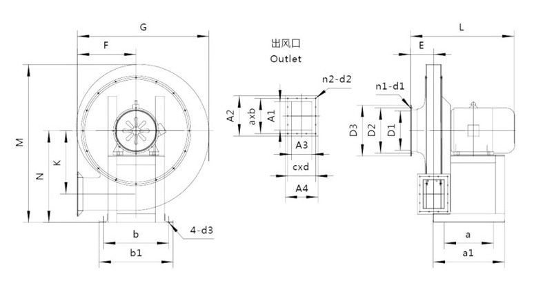
产品为人工实物测量会有一定误差,相关数据仅作参考,以收到的实物为准。 单位Unit: mm(毫米)
| 机号 | |||||||||||
|---|---|---|---|---|---|---|---|---|---|---|---|
| 进风口尺寸 Air inlet | 出风口尺寸 Vent | ||||||||||
| Model | D1 | D2 | D3 | n1-d1 | A1 | A2 | A3 | A4 | a*b | c*d | n2-d2 |
| 3.15 | 147 | 180 | 210 | 8-Φ8 | 107 | 168 | 93 | 154 | 69.5*2 | 60*2 | 8-Φ11 |
| 3.55 | 165 | 197 | 215 | 130 | 198 | 96 | 155 | 55*3 | 63*3 | 10-Φ11 | |
| 4 | 186 | 211 | 244 | 135 | 202 | 110 | 170 | 57*3 | 70*2 | 10-Φ11 | |
| 4.5 | 208 | 230 | 253 | 145 | 212 | 110 | 170 | 61*3 | 70.5*2 | 10-Φ11 | |
| 5 | 227 | 258 | 285 | 163 | 230 | 133 | 194 | 66*3 | 81*2 | 10-Φ11 | |
| 5.6 | 258 | 285 | 305 | 193 | 251 | 163 | 223 | 75*3 | 64.3*3 | 12-Φ11 | |
| 6.3 | 290 | 323 | 350 | 205 | 270 | 165 | 226 | 81*3 | 65*3 | 12-Φ11 | |
| 7.1 | 326 | 355 | 395 | 8-Φ11 | 227 | 294 | 163 | 232 | 54*5 | 69*3 | 16-Φ11 |
| 机号 | ||||||||||||
|---|---|---|---|---|---|---|---|---|---|---|---|---|
| 外形及安装尺寸 Shape and installation dimensions | ||||||||||||
| Model | G | M | L | F | N | K | E | a | b | a1 | b1 | d1 |
| 3.15 | 484 | 586 | 362 | 221 | 336 | 234 | 74 | 330 | 120 | 355 | 245 | Φ11 |
| 3.55 | 549 | 660 | 397 | 255 | 370 | 254 | 86 | 365 | 140 | 397 | 260 | |
| 4 | 620 | 700 | 466/426 | 283 | 400 | 286 | 98 | 350 | 200 | 385 | 360 | |
| 4.5 | 692 | 780 | 567/492 | 325 | 450 | 330 | 109 | 390 | 240 | 430 | 410 | |
| 5 | 763 | 880 | 706/576 | 362 | 500 | 352 | 120 | 450 | 340 | 500 | 440 | |
| 5.6 | 820 | 980 | 768/723 | 367 | 570 | 400 | 133 | 484 | 350 | 532 | 447 | |
| 6.3 | 933 | 1100 | 908/783 | 426 | 645 | 450 | 148 | 570 | 450 | 625 | 567 | |
| 7.1 | 1037 | 1230 | 870 | 460 | 690 | 508 | 170 | 600 | 480 | 710 | 570 | Φ20 |
欢迎进入“万通风机”官方网站
Welcome to Wantong Xingfeng official website

|
广州市万通通风设备有限公司 广州市万通通风设备有限公司(注册商标:万通星风)是一家研发、生产、销售、安装通风设备、大气污染防治设备的多元化专业性企业。产品广泛用于:电镀、化工、电子、电气、线路板、机械、电站、电厂、科研、医院、实验室、矿业、冶炼、橡胶、林业、皮革、纸业、陶瓷、模具车间、汽车制造,新能源机械等配套以及各种含有腐蚀性气体的场合。每一个产品都见证了万通的品质,让万通立足全国,走向世界!经过十几年发展“万通星风”已汇聚了一群技术精湛,经验丰富的专业技术人员,引进消化国内外先进技术,是国内拥有自主研发大气污染防治设备、防腐风机能力的厂家。“国际品质、万通打造” 全国服务热线:400-8088-128 |
广州总公司
Guangzhou General Corporation

|
电话:15099956818/13318895737 |

|
传真:+86-020-34734593 |

|
邮箱:wantongfj@163.com |

|
在线QQ客服: |

|
地址:广州市番禺区沙湾镇动车街33号之二 路线:广州地铁3号线到番禺广场站下,换乘公交车番68路、到古东村总站下。 |
||
区域经理
regional manager
| 区域情况 | 区域经理 | 联系电话 |
微 信 与 手 机 同 号 |
| 全球各地,公司老总 | 何其锐 | 13318895737 | |
| 全国各地,销售总经理 | 何其福 | 15099956818 | |
|
|
公司地图
Company map

销售服务热线
15099956818/13318895737
总部地址:广州市番禺天安节能科技园15号总部大楼304室
工厂地址:广州市番禺区沙湾镇动车街33号之二
传真号码:020-34734593


广州市万通通风设备有限公司
销售电话:
ONLINE CONSUL TATION


